Small Size Flatbed Inkjet Printer Manufacturer

3D Raised Logo Artwork Guide: White, CMYK and Varnish Layer Setup
A 3D raised-logo file should not be treated as one flat image.
For a professional raised apparel badge, the artwork needs to be separated into several production functions:
CMYK → visible color
Structural White → raised height and geometry
Varnish → gloss and surface finish
Cut Line → final badge shape
These layers must remain perfectly aligned when they are handed to the RIP, printed repeatedly, UV cured and finally contour cut.
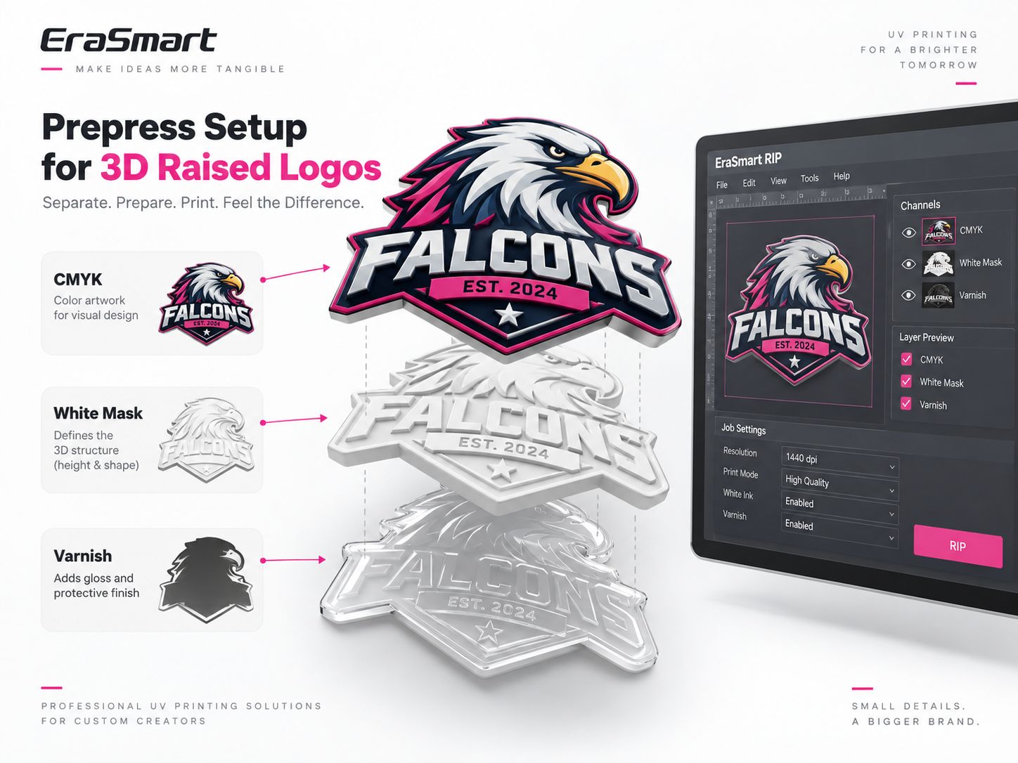
In the EraSmart 3D textile workflow, this artwork is then printed with a flexible UV ink system using high-build white ink, high-flexibility CMYK and varnish, followed by contour cutting and transfer with a compatible TPU heat-transfer system.
If you are new to the production process itself, start with How to Make 3D Raised Logos with a UV DTF Printer: Complete Workflow.
A 3D Raised Logo Is Not One Image
A normal digital image mainly describes what the customer sees.
A 3D production file needs to describe both appearance and manufacturing structure.
That means the printer and cutting system need more information than a single flattened PNG.
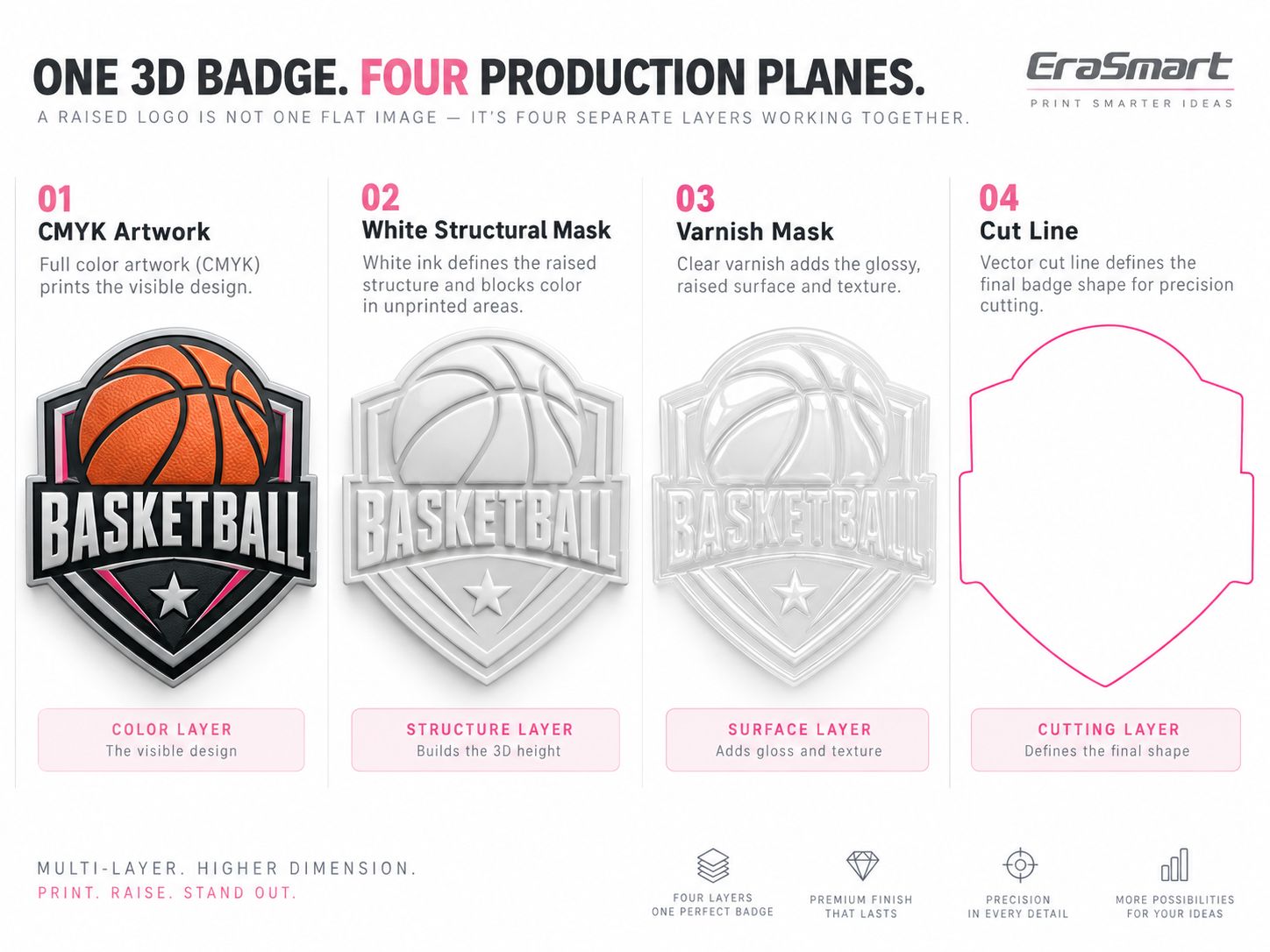
A typical raised-logo job contains four separate production planes.
| Production Plane | Main Function |
|---|---|
| CMYK Artwork | Defines the visible color, text, graphics and gradients |
| Structural White Mask | Defines where the physical raised structure is built |
| Varnish Mask | Defines where gloss or clear finishing is applied |
| Cut Line | Defines the final outside contour for cutting |
The important point is that these four planes do not necessarily have identical geometry.
For example, the color artwork may contain small stars and fine text that do not need to be physically raised.
The varnish may cover only selected highlights.
And the cut line normally sits outside the printed structure rather than following every internal detail.
This is why prepress matters.
Start with the Finished Badge, Not the RIP Channel Name
A common mistake is to open the RIP first and immediately ask:
Which channel should be W1?
or:
Which spot color should be called Varnish?
That is backwards.
Channel naming can vary by RIP, printer profile and ink configuration.
The artwork should first answer four production questions:
- What should the customer see?
- Which parts should physically stand up?
- Which parts should be glossy?
- Where should the final badge be cut?
Only after these decisions are clear should the file be mapped to actual printer channels.
The safest rule is:
Design the production function first. Map the channel second.
Do not assume that a channel name such as Spot1, W1 or V1 has the same meaning in every RIP profile.
Always confirm the actual ink mapping in the RIP before printing.
Step 1: Prepare the CMYK Artwork
Start with the finished visual design.
For logos, emblems and lettering, vector artwork is usually preferred because it provides cleaner edges and scales without losing detail.
Raster artwork can also be used when appropriate, but it should have sufficient resolution at the final physical output size.
Before creating masks:
- set the final badge dimensions
- clean unnecessary objects
- outline or package fonts as needed
- remove accidental background pixels
- confirm transparency
- simplify extremely tiny isolated elements
- make sure important details will survive the final print and cut size
The CMYK layer should describe the visible design only.
It does not automatically determine which areas need physical height.
Step 2: Create the Structural White Mask
The structural white mask is one of the most important parts of a 3D raised-logo file.
In this workflow, white ink is not used only as an opacity underbase.
Repeated high-build white ink layers create the physical 3D structure.
For a deeper technical explanation of this process, see How White Ink Layers Create 3D Raised Effects in UV DTF Printing.
White Mask Defines Geometry, Not Color
Think of the white mask as a structural drawing.
It answers:
Which areas should have raised height?
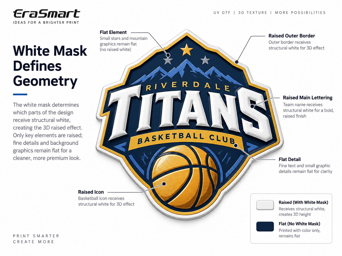
For a sports badge, you might choose to raise:
- the outer border
- large team lettering
- the main basketball or icon
- selected decorative elements
While leaving:
- tiny stars
- very fine text
- background texture
- small gradients
relatively flat.
This often creates a cleaner and more premium result than simply raising every pixel in the artwork.
Do Not Automatically Duplicate the Entire CMYK Shape
Copying the complete color artwork into the white mask can make the finished badge unnecessarily heavy and visually flat.
A good raised design normally has hierarchy.
Some elements stand higher.
Some remain visually supportive.
The white mask should therefore be deliberately designed.
Does a White Mask Control Height?
Primarily, the artwork mask defines where structural white is printed.
The actual height depends on the production profile:
- number of white passes
- ink output
- curing strategy
- film
- target thickness
- printer configuration
Do not assume that a darker or lighter grayscale value automatically creates a specific physical height unless the actual RIP profile has been configured and tested to interpret it that way.
For standard production, it is safer to treat:
mask geometry = where
and:
RIP / print profile = how much
Step 3: Control White Choke and Registration
White registration becomes increasingly important when the same structural layer is printed repeatedly.
If the white mask extends slightly beyond the CMYK artwork, a visible white halo may appear around the finished design.
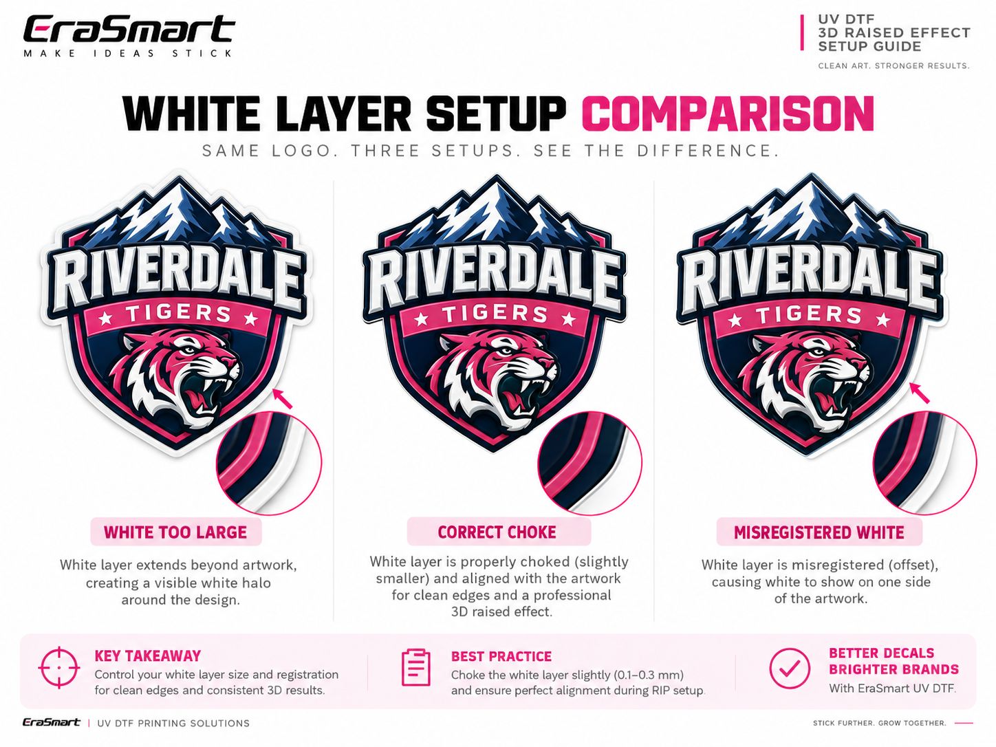
There are three useful situations to understand.
White Too Large
The structural white extends outside the visible color.
Possible result:
- visible white edge
- uneven border
- cheap-looking finish
Correctly Choked White
The structural white is slightly controlled inside the visible artwork.
This can help hide minor registration tolerances and produce a cleaner visible edge.
Misregistered White
The white mask itself may be correctly sized but shifted relative to CMYK.
This causes one side of the graphic to expose white while the opposite side loses support.
That is a registration problem, not simply a choke problem.
How Much White Choke Should You Use?
There is no universal value that should be copied into every job.
The correct amount depends on:
- printhead registration
- output resolution
- artwork scale
- edge complexity
- total white buildup
- film stability
- RIP profile
Avoid treating a fixed pixel or millimeter value from another machine as an EraSmart standard.
Instead, create a small production test and inspect the final raised edge.
EraSmart’s EraRIP software can be used with compatible printer profiles to manage white, color and spot-layer output during production.
Step 4: Create the Varnish Mask
Varnish is a separate production decision from structural white.
In the EraSmart 3D textile workflow:
White builds most of the height.
Varnish controls the visible surface finish.
The varnish mask determines where clear ink is applied.
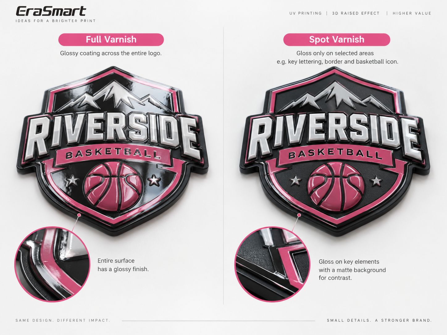
There are two common design approaches.
Full Varnish
Varnish covers most or all of the visible badge.
This creates:
- consistent gloss
- strong reflective appearance
- unified premium surface
This can work well for highly polished badge designs.
Spot Varnish
Only selected areas receive clear varnish.
For example:
- main lettering
- border
- basketball
- icon
- metallic-style accent
while other areas remain visually flatter.
This creates stronger contrast between glossy and non-glossy areas.
Should Varnish Match the White Mask?
Not necessarily.
The White Mask answers:
Where should the physical 3D structure exist?
The Varnish Mask answers:
Where should the surface be glossy or visually emphasized?
These are two different questions.
A logo may have a raised outer border without requiring full gloss on that border.
Likewise, a flat detail may receive varnish purely for visual contrast.
This is why White and Varnish should remain separate production planes.
For a broader explanation of the functions of white, CMYK and varnish, see the EraSmart UV Ink Guide.
Step 5: Create the Contour Cut Line
Unlike a conventional hard-surface crystal label, the EraSmart 3D apparel workflow includes contour cutting before heat transfer.
The cut path should therefore be prepared as its own vector production object.
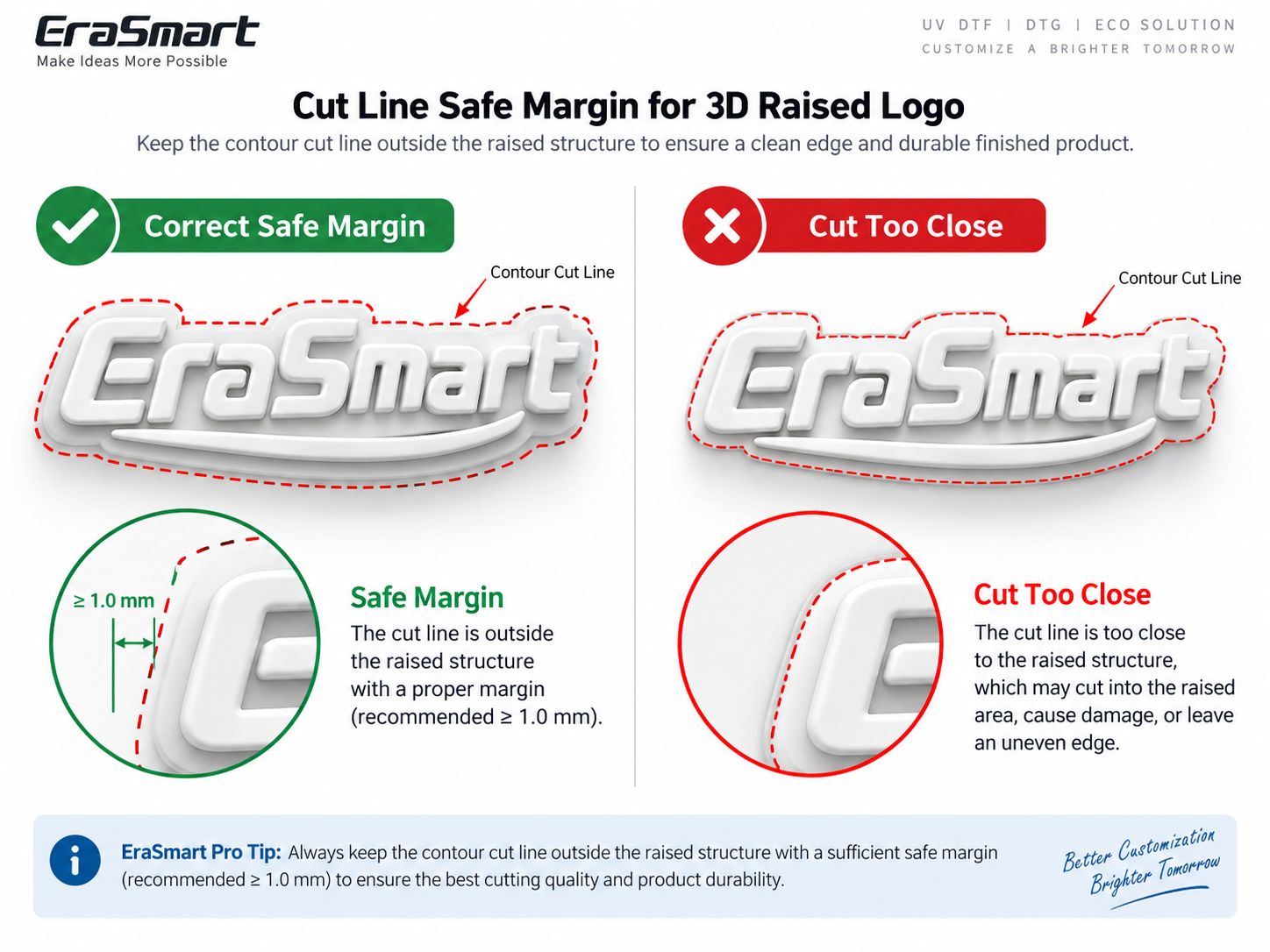
The cut line should normally stay outside the raised structure.
If the blade or cutting path runs too close to a high-build area, potential problems include:
- cutting into the raised ink
- chipped edges
- uneven perimeter
- reduced bonding area
- edge lifting after transfer
Do Not Hard-Code a Universal Safe Margin
The ideal distance depends on:
- badge geometry
- total raised thickness
- cutting machine
- blade
- film
- material feeding accuracy
Use a tested contour allowance for the actual production system instead of copying one universal value.
The design principle is simple:
The cutting path should protect the raised structure, not intersect it.
Step 6: Keep Every Production Plane Registered
CMYK, White, Varnish and Cut Line should all originate from the same master artwork.
They should retain:
- identical overall dimensions
- identical scale
- identical orientation
- identical origin
- consistent positioning
A small resizing mistake may look insignificant on screen.
After several white passes, color printing, varnish and contour cutting, that small error can become highly visible.
Typical Registration Problems
A White Mask at 99.8% size compared with CMYK may create an inconsistent structural border.
A Varnish Mask shifted slightly may make highlights appear off-center.
A Cut Line based on an older version of the artwork may cut directly through the finished design.
Keep all production objects linked to one final approved master.
Step 7: Export the Artwork for RIP
There are two practical ways to prepare a job.
Workflow A: Let the RIP Generate Production Layers
For relatively simple artwork, you can import the main artwork and use RIP functions to generate or control the white and spot output.
This can be efficient for repetitive production.
Workflow B: Supply Dedicated Designer-Created Masks
For more advanced 3D badges, the designer can prepare:
- CMYK artwork
- Structural White Mask
- Varnish Mask
- Cut Line
before the file reaches the RIP.
This gives much more control over which elements are raised and which areas receive varnish.
Neither method is automatically better.
The right approach depends on the design complexity and production workflow.
File Format Considerations
Do not choose a file format only because another shop uses it.
The target RIP profile should determine the final handoff format.
In general:
- vector/PDF workflows are useful for logos and cut paths
- transparent raster artwork can work for image-based CMYK content
- cut lines are normally easiest to control as vectors
- spot information must survive import correctly
Before production, always verify the imported result inside the actual RIP.
Step 8: Map Production Planes to the Correct Ink Channels
The artwork layer name and the physical printer ink channel are not necessarily the same thing.
For example, the designer may call a layer:
STRUCTURAL_WHITE
but the printer profile may map white through a completely different internal channel name.
The correct workflow is:
- import the artwork
- identify each production plane
- map White to the actual high-build white channel
- map CMYK to the flexible color channels
- map Varnish to the clear ink channel
- confirm the cut object is handled by the cutting workflow rather than printed as visible artwork
- verify the complete job in preview
For the 3D textile process, the machine itself must support independent:
High-Build White + Flexible CMYK + Varnish
output.
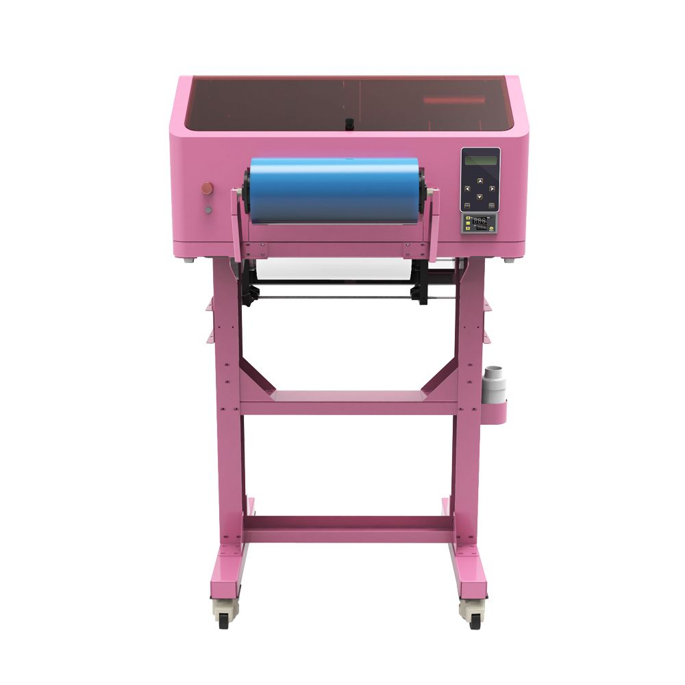
The EraSmart A2 UV DTF Printer can be configured for this workflow when paired with the appropriate flexible UV ink, TPU film and production setup.
Step 9: Verify Mask Polarity
A White Mask that looks visually correct in a design application can still print incorrectly if the RIP interprets the mask polarity differently.
Depending on the software workflow:
- white may represent ink
- black may represent ink
- transparency may represent no ink
- spot objects may be interpreted independently of grayscale appearance
Do not assume.
Check the RIP preview.
The same warning applies to varnish.
A good prepress operator verifies actual output logic rather than trusting how the mask looks in Photoshop or Illustrator.
Step 10: Preview Every Layer Before Printing
This is the last and most important prepress check.
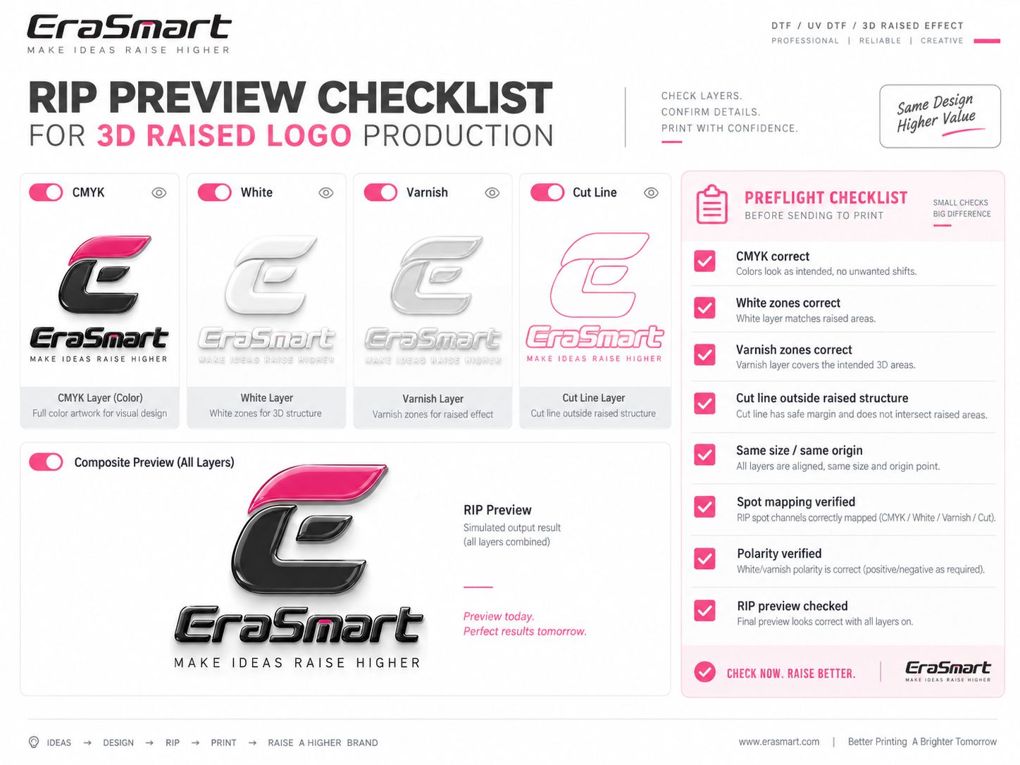
Turn the production planes on and off one by one.
Check CMYK Only
Confirm:
- color artwork is correct
- no hidden objects remain
- no unwanted background is present
- size is correct
Check Structural White Only
Confirm:
- only intended raised elements are selected
- no fine details are accidentally included
- no required structural areas are missing
Check Varnish Only
Confirm:
- full or spot varnish matches the intended finish
- gloss areas are not accidentally covering unwanted zones
Check the Cut Line
Confirm:
- final shape is correct
- cut path remains outside critical raised structure
- no hidden duplicate cut paths exist
Check the Composite Preview
Finally combine the layers and inspect:
- White vs CMYK registration
- white halo risk
- varnish alignment
- total badge geometry
- cut-line relationship
Do not start a high-build multi-pass print until the composite preview makes sense.
Example: Preparing a Sports Team Badge
Consider a basketball club badge with:
- outer gold border
- large team name
- basketball icon
- small stars
- fine subtext
- dark background
A practical separation might look like this.
CMYK
Contains all visible artwork:
- purple background
- gold border
- orange basketball
- white/gold lettering
- stars
- fine text
Structural White
Used under:
- main team name
- large outer border
- basketball
- selected primary emblem elements
Small decorative stars and fine secondary text may remain flatter.
Varnish
Could be applied to:
- main lettering
- gold border
- basketball
while leaving the background less glossy.
This creates a stronger visual hierarchy.
Cut Line
Follows the overall outside shape of the badge while maintaining enough clearance from the high-build structure for reliable contour cutting.
The result is not just a printed logo.
It is an engineered badge.
Large Raised Logos vs Fine Details
Artwork that looks excellent as a flat graphic does not automatically make a good 3D badge.
Large Letters
Usually tolerate stronger height and provide clear sidewalls.
Broad Borders
Often work well as raised structural elements.
Small Text
May lose clarity if the raised build becomes too thick.
Fine Lines
Need careful testing because excessive structural buildup can close gaps or soften visual edges.
Tiny Isolated Objects
May not justify being raised at all.
This leads to an important design principle:
Design for the final physical process instead of converting a flat logo into 3D at the last minute.
Common 3D Raised Logo Artwork Mistakes
Mistake 1: Treating Transparency as the White Mask
Transparency only describes whether artwork is visible.
It does not automatically define a structural white production plane.
Always confirm the actual White Mask or RIP-generated white output.
Mistake 2: Raising Every Part of the Design
This removes visual hierarchy and can increase:
- ink consumption
- print time
- stiffness
- registration difficulty
Raise only the elements that need dimensional emphasis.
Mistake 3: White Extends Outside the CMYK
This can create a visible white halo.
Use appropriate white choke and confirm registration.
Mistake 4: Varnish Is Automatically Copied from White
White and Varnish serve different purposes.
The White Mask controls structure.
The Varnish Mask controls finish.
Mistake 5: Cut Line Is Too Close to the Raised Area
This can damage the structural edge during contour cutting.
Mistake 6: Production Layers Have Different Dimensions
Even a small size change can create visible registration errors.
Mistake 7: Spot Mapping Is Not Verified
A correctly designed mask can still print incorrectly if it is mapped to the wrong physical channel.
Mistake 8: Mask Polarity Is Assumed
Always verify White and Varnish output in the RIP preview.
Preflight Checklist Before Printing
Before starting a 3D raised-logo production job, confirm the following:
- CMYK artwork is final
- final physical size is correct
- Structural White Mask covers only intended raised areas
- White choke is appropriate
- Varnish coverage is intentional
- Cut Line is correct
- Cut Line stays clear of critical raised areas
- all planes share the same scale
- all planes share the same origin
- spot/channel mapping is correct
- White polarity is verified
- Varnish polarity is verified
- composite RIP preview is correct
If any one of these is wrong, the error can become more obvious after repeated white-layer printing.
Artwork Is Only One Part of the 3D System
Correct file preparation is essential, but artwork alone does not create a durable textile badge.
The complete EraSmart 3D raised-logo process also depends on:
- High-Flexibility UV Curable Ink for Textile / 3D Embossed UV Ink
- high-build flexible white ink
- flexible CMYK
- varnish
- TPU Hot Melt Film for 3D Transfer
- Flexible UV-DTF Base Film
- TPU Hot Melt Adhesive Film
- controlled LED-UV curing
- white-ink circulation and stirring
- contour cutting
- textile heat pressing
This is fundamentally different from a conventional UV DTF crystal-label workflow that uses standard UV ink and Crystal Label A/B Film for hard surfaces.
For a complete explanation of the textile application, see the EraSmart 3D Raised Logo Printing with UV DTF Technology.
From Artwork to Finished 3D Logo
Once the prepress file is correct, the production sequence becomes:
Prepare CMYK Artwork
↓
Create Structural White Mask
↓
Create Varnish Mask
↓
Create Cut Line
↓
Map the Production Planes in RIP
↓
Build the High-White Structure
↓
Print Flexible CMYK
↓
Apply Varnish
↓
Controlled UV Cure
↓
Contour Cut
↓
Heat Transfer to the Garment
The artwork phase determines whether every later step starts from the correct geometry.
A well-prepared file reduces trial-and-error on the printer and makes the complete workflow far more repeatable.
Final Takeaway
A professional 3D raised-logo file is not simply a colorful logo with a white background.
It is a production package.
CMYK defines what the customer sees.
Structural White defines where physical height is built.
Varnish defines the surface finish.
The Cut Line defines the final product shape.
The best results come when these four production planes are deliberately designed, precisely registered and verified inside the RIP before the first high-build white pass begins.
If you want to understand what happens after prepress, continue with How to Make 3D Raised Logos with a UV DTF Printer: Complete Workflow.
For the technical reason the White Mask creates real physical height, read How White Ink Layers Create 3D Raised Effects in UV DTF Printing.
And if you are building the complete production system, explore the EraSmart A2 UV DTF Printer and EraRIP software.
Frequently Asked Questions
What layers do I need for a 3D raised logo?
A typical professional job needs CMYK artwork, a Structural White Mask, a Varnish Mask and a contour Cut Line.
Should my White Mask be identical to the CMYK artwork?
Not necessarily. The White Mask should define the areas that need physical raised structure. Small details, background graphics or fine text may remain flatter even though they appear in the CMYK artwork.
Does the White Mask control the final height?
The mask primarily controls where structural white is printed. Actual height depends on the RIP and print profile, including white passes, ink output, curing and consumables.
What is white choke?
White choke slightly controls the white area relative to the visible color boundary to reduce the chance of a visible white halo caused by registration tolerances.
How much white choke should I use?
There is no universal value. It should be tested according to the printer profile, artwork size, registration accuracy, film and white-layer buildup.
Should the Varnish Mask match the White Mask?
Not automatically. White defines structural height, while varnish defines surface gloss and finishing. Full varnish and spot varnish can both be used depending on the design.
Should every part of the logo be raised?
No. Selective raised areas often produce a cleaner and more premium result than giving every fine detail the same structural height.
What is the Cut Line for?
The Cut Line defines the final outside badge shape for contour cutting before textile heat transfer.
Can the Cut Line touch the raised structure?
It is generally better to maintain a safe separation so the cutting process does not damage high-build ink edges. The exact margin should be validated for the real cutting and material system.
Does black always mean “print white ink” in the White Mask?
No. Mask polarity depends on the software and RIP workflow. Always verify the actual White output in the RIP preview.
Can EraRIP generate white and spot output?
EraRIP can be used with compatible EraSmart printer profiles to manage white, color and spot-layer output. The final channel mapping should always be checked against the actual printer and ink configuration.
Is this artwork setup also used for ordinary UV DTF crystal labels?
Some basic concepts such as CMYK, White and Varnish separation are related, but the 3D textile workflow uses a different consumable and finishing system. It uses flexible 3D UV ink, TPU transfer materials, contour cutting and heat pressing rather than standard Crystal Label A/B Film hard-surface transfer.
MAY BE YOU LIKE ALSO
Copyright 2020 © EraSmart. | Sitemap